Intro
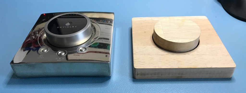
I’m the lucky owner of a Devialet Expert Pro 250 (which started as the D Premier many moons ago) driving a pair of Martin Logan CLX Art. (Yes, it’s as good as the many raving reviews say. If you have to chance to buy one, don’t hesitate).
But what has this to do with this blog post? Well, one of the nice things of the Devialet is its remote control and more specifically, the way they implemented the volume control. The huge knob allows you to change the volume in a very natural and satisfying way. Turn up the volume in the truest sense of the word. And this was something I really missed for my Sony TA-F501ES which are powering my small speakers in the man cave. Especially the way Sony implemented the volume up/down is extremely annoying. When you press the up/down buttons, the volume changes in steps of 0.5dB, which are very small steps. However, if you press the up/down buttons more than 3 times per second (which happens a lot because those 0.5dB steps are so small) then the volume suddenly changes in steps of 6 dB, which is really too much. Before you know it you have changed the volume by 12 or even 18 dB because you’re frantically pushing up/down.


So, the idea started to ripen to build a dedicated volume control for this amplifier and if possible avoid those 6 dB jumps in volume. For this I decided to start with an Arduino Uno and see how far I got with that platform. As it turned out, it was possible to build a functional remote with a very low power consumption where batteries should last years.

Remote control codes
First task was to find out what the codes were for volume Up/Down for this particular
amplifier. And there I hit the first problem. It must be that this wasn’t a very popular
amplifier since none of the databases had an entry for its remote control (an RM-A AUU012).
Luckily, it’s not hard to find out which codes an IR remote is sending with the excellent IRremote library by Ken Shirriff and Rafi Khan.
After a few minutes I already found the needed 12 bit codes:
- Up: 0x486
- Down: 0xC86
This is going to be a minimal remote control. No other buttons to e.g. change the input are present. It’s build for one thing and it should do it well.
Hardware
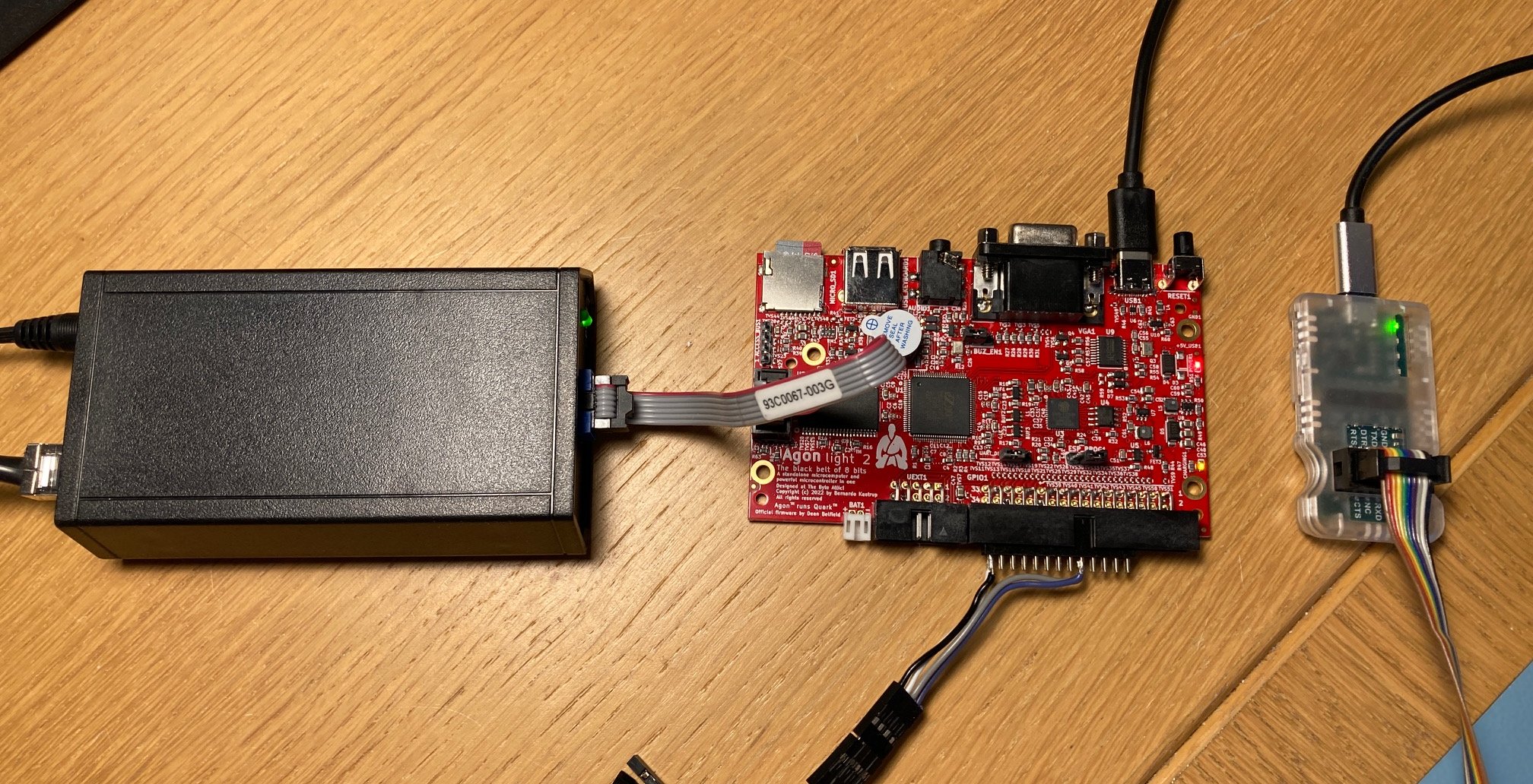
Obviously, I can’t take an of the shelve Arduino Uno since this is intended to be powered by batteries. All Arduino boards contain at least a voltage regulator and several other chips that take up too much power. So I took the Arduino schematics and removed everything that was not absolutely needed and I came to the following design:

I did add some space to add pin headers for the I/O I don’t use, a reset switch and place for resistors to the Tx/Rx pins that so that the PCB can be reused for other projects as well (helps recycling those PCB’s you get too much from your favourite PCB manufacturer).
With a little bit of extra effort, it’s easy to dimension the PCB in such a way it will fit nicely in its future enclosure. There’s a small cut away as well for the sending IR LED and the rotary encoder is dead centre of course.

Enclosure
Not being able to mill big pieces of aluminium I decided to build the body of the remote control from wood. Since I still have quite some 18 mm thick rubberwood leftovers when I build my bookshelves I decided to give that a try.
The body
Since the Devialet remote control is about as perfect as you can get, I took over its outer dimensions which is 120 by 120 mm. I used OpenSCAD to draw a template that then can be used by EstlCAM to generate the gcode for the CNC mill:


Playing a bit with the tolerances made it so that the PCB was such a tight fit in the body that no screws or glue was necessary to keep the PCB in place.


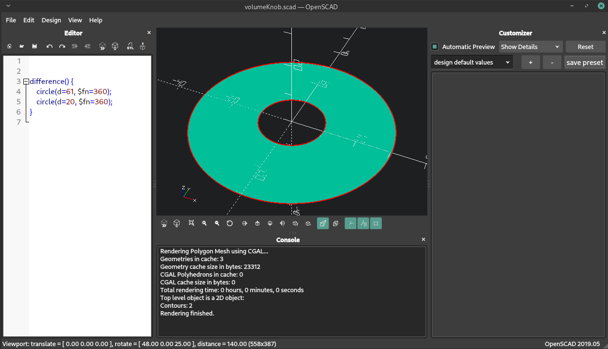
The control knob
The knob has a diameter of 61 mm. But here I’m running into a practical problem. The shaft of the rotary encoder is D shaped instead of a perfect circle. That’s impossible to mill with a 1/8" mill. And also here I wanted a tight fit so that I would not need any screws or glue to keep the knob securely attached to the shaft of the rotary encoder.
I solved this by using my CNC mill to mill a 61 mm cylinder and pocket a 20 mm cylinder 16 mm deep along its centre axis. The 20 mm pocket is then filled with a 3D printed cylinder (16 mm high) with a D shaped hole along the centre axis.
For the templates, I used openSCAD again:


Software
The source code for this (platformIO) project can be found on BitBucket (see links at the end of this post).
The project uses 3 libraries:
- IRremote by Ken Shirriff and Rafi Khan
- Encoder by Paul Stoffregen
- Low-Power by Rocket Scream Electronics
The IRremote library is used to send out the up/down control codes via the IR LED connected to pin 3 (default pin). I found that the Sony receiver is not happy when you only send the IR code once (nothing happens in that case) and prefers to have a quick burst of codes send rapidly after each other with a very short pause in between. That’s why you see in the code that I send the up/down codes 5 times with a short 15 millisecond pause in between.
For the rotary encoder I used the Encoder library. The rotary encoder is connected to pin 5 and 6. I also connected the push switch of the rotary encoder to pin 4. This allowed me to use the volume control in 2 modes. In the default (start up) mode, the remote control will send out a maximum of 3 up/down bursts per second. This prevents having those huge, sudden 6 dB changes of volume when you turn the knob too fast. If you push the knob, this safety measure is disabled and up/down codes will be send continuously. Push the knob once again, and you return back to the safe mode.
Since the remote control runs from batteries, it’s of course important to get the lowest possible power consumption. For this I used the Low Power library and was able to obtain excellent results.
Without taking any power saving measures, the ATmega328 consumes around 16mA (at 5V). Experimenting with just putting the ATmega328 in idle:
static void lowPowerSleep(period_t period)
{
    LowPower.idle(period, ADC_OFF, TIMER2_OFF, TIMER1_OFF, TIMER0_ON,
                  SPI_OFF, USART0_OFF, TWI_OFF);
} /* end lowPowerSleep */
helped only a little bit and power consumption remained way too high and batteries would be depleted in a matter of days. Not good.
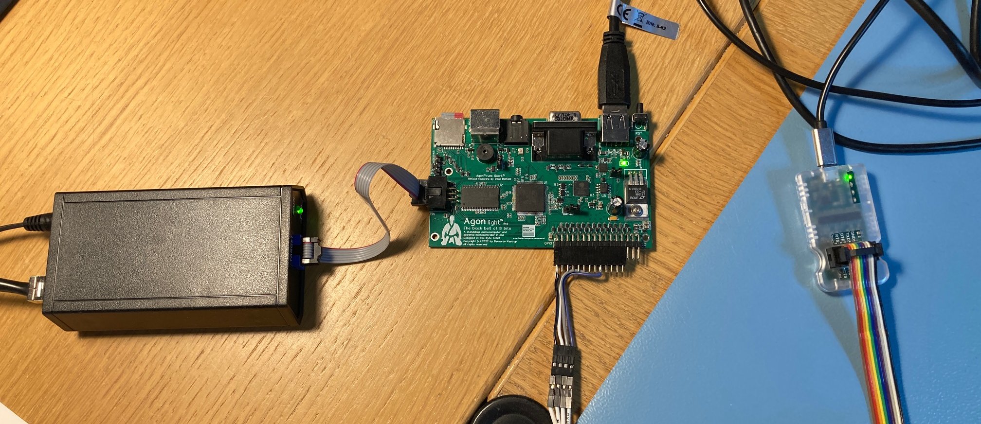
So time to take more drastic measures and really power down the ATmega328. But in that case, the ATmega328 needs an external interrupt to wake up again and I did not foresee that in my PCB design. Luckily it was as simple as adding a small wire from pin 2 (which I used for the wake up interrupt pin) to one of the pins the rotary encoder was connected to (pins 5 and 6). When you turn the rotary encoder, pin 5 and 6 will go LOW and that can be used to wakeup the ATmega328 as well. So I added a small wire from pin 5 to pin 2 as you can see here:

I added this bit of code which gets called after 2 seconds of inactivity:
#define wakeUpPin                  2    // Use pin 2 as wake up pin

static void powerDown()
{
    attachInterrupt(0, wakeUp, LOW); // Allow wakeUp pin to trigger interrupt on low.

    #ifdef myDEBUG
    Serial.println("PowerDown");
    #endif

    LowPower.powerDown(SLEEP_FOREVER, ADC_ON, BOD_ON);

    detachInterrupt(0);
} /* end powerDown */
which just attaches pin 2 to an interrupt and then powers down. So what’s the result? Well not bad at all. The quiescent current dropped to 137 μA.

But I knew the ATmega328 could do a lot better than that. Luckily, there is an easy fix. I accidentally left the ADC and Brown Out Detector ON during power down.
#define wakeUpPin                  2    // Use pin 2 as wake up pin

static void powerDown()
{
    attachInterrupt(0, wakeUp, LOW); // Allow wakeUp pin to trigger interrupt on low.

    #ifdef myDEBUG
    Serial.println("PowerDown");
    #endif

    LowPower.powerDown(SLEEP_FOREVER, ADC_OFF, BOD_OFF);

    detachInterrupt(0);
} /* end powerDown */
Modifying and uploading the new code dropped the quiescent current to just 0.11 μA:

With such a low quiescent current, batteries should last years.
Finishing up
From the ATmega328 data sheet we know that its operating voltage can range from as low as 1.8 V to 5.5 V. So the remote controller should be able to operate with just 2 AAA batteries (the PCB design I made has room for 3 AAA’s). Trying it out and indeed it did.
Since the body of the volume control is quite slim (only 18 mm in height) the battery holder would stick out if I mounted it on the PCB itself. So I cut away a part of the PCB big enough to let a double AA battery fit through:


To protect the rubberwood, give a satin silky smooth feeling and let the wood grain stand out a bit more, I applied a bit of oil to the rubberwood:

And that’s it. The remote control now sits proudly on my desk, in arms reach, and changing the volume experience has become a lot more pleasant. It’s not perfect because of the annoying volume jumps Sony decided to use but a lot better nevertheless.
As usual, there are still improvements that could be made. E.g. the remote control could benefit from being a bit heavier and maybe I should consider of trying to make an enclosure from concrete like I did for my rain barrel level meter.
Using IR dictates that remote control and amplifier need to see each other. I could consider using e.g. a Zigbee transceiver (which the Devialet is actually using) to work around that. But in that case, I would need to design the receiving end for the amplifier as well. And that becomes suddenly a much bigger project.